Group assignment(Read more about the group assignment)
For our group assignment we must use the test equipment in your lab to observe the operation of a microcontroller circuit board.We don't have a oscilloscope in the lab so we use a digital voltmeter to observe the operation.
The Fab academy board design I redsigned to make my board.
Invidual Assignment
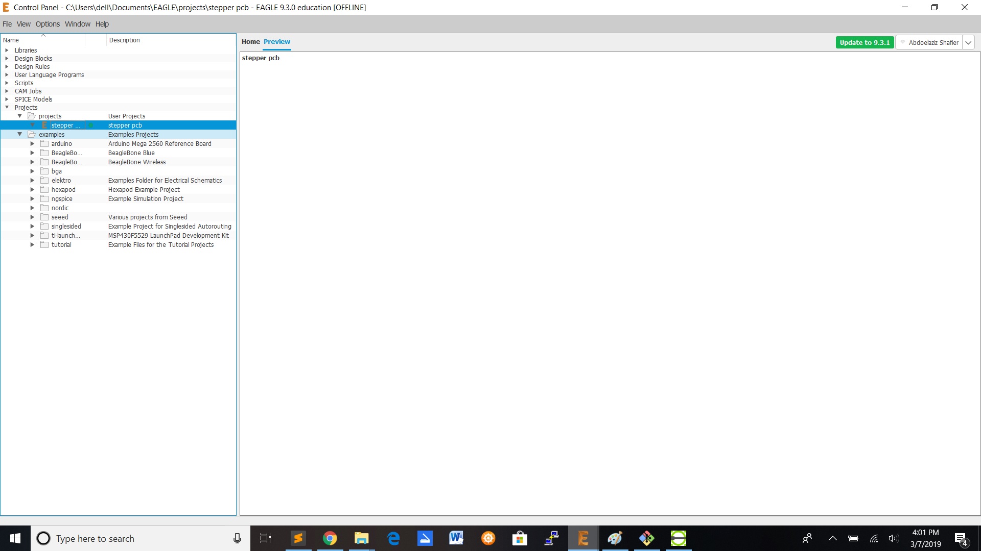
For redesigning the board i used the software Autodesk Eagle to redraw the board.
First you have to install the Fab academy library into your Eagle or KiCad software to get the components we need to design the board.The Fab Library you can download on the Fab Academy site.
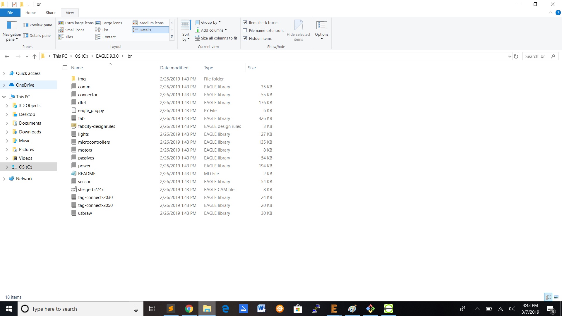
When you downloaded the library ,you have to install it into the Eagle or KiCad software by copying the files to the Eagle/KiCad library folder.You can find the eagle folder where you installed the software.
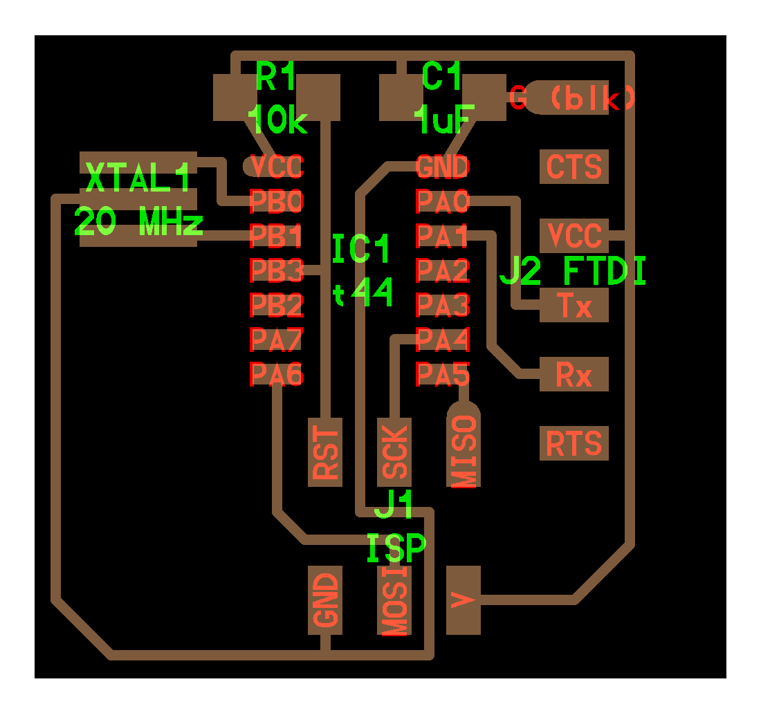
Redraw the board
For our invidual assignment we had to redesign the echo hello world board and program it.
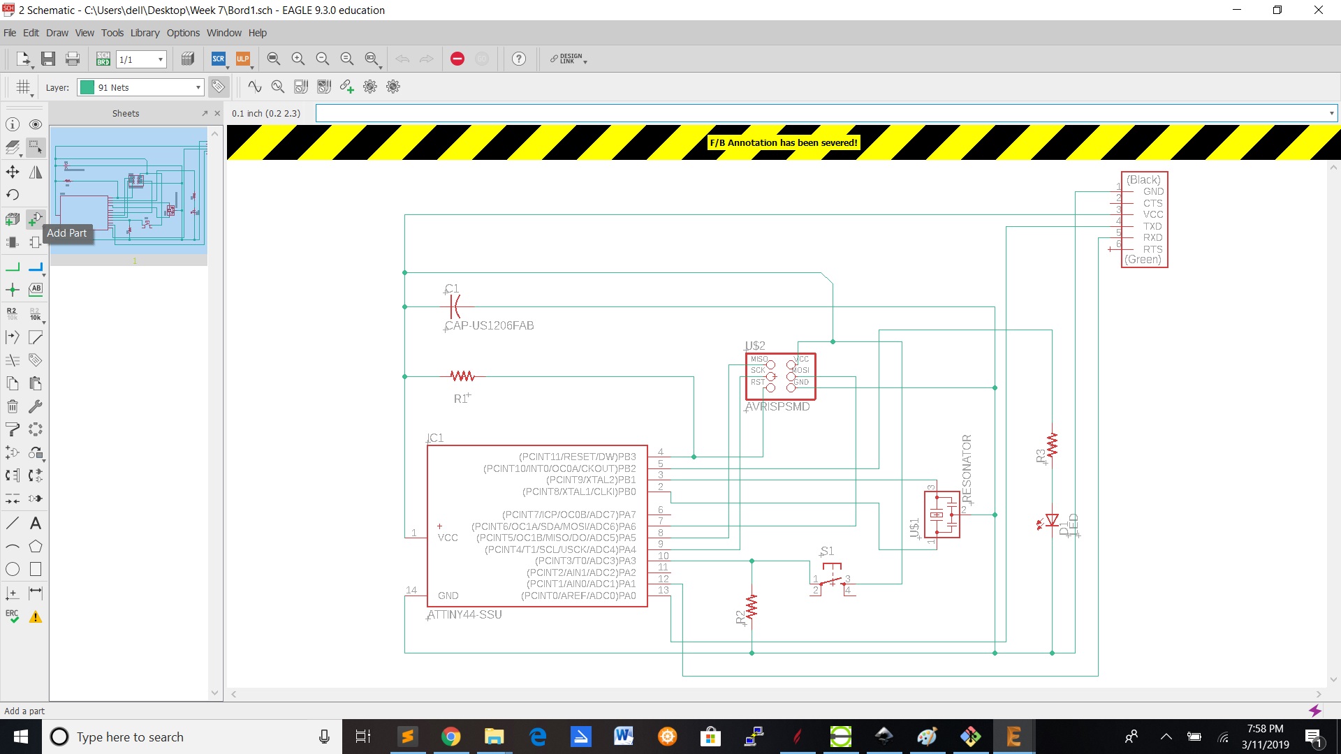
To add a component ,click on the add button.
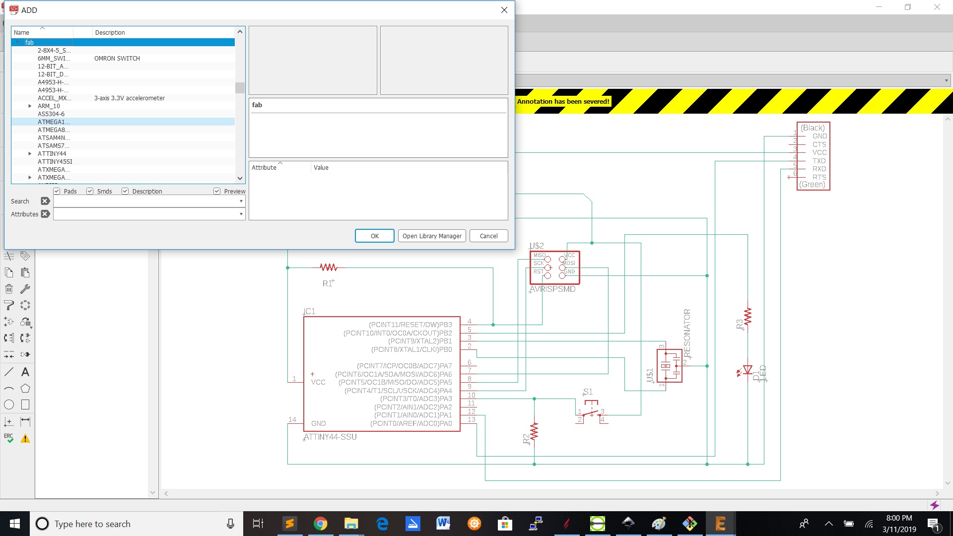
Search for the component in the library(recently added the fab library in eagle).

To connect the components ,click on net on the left panel.
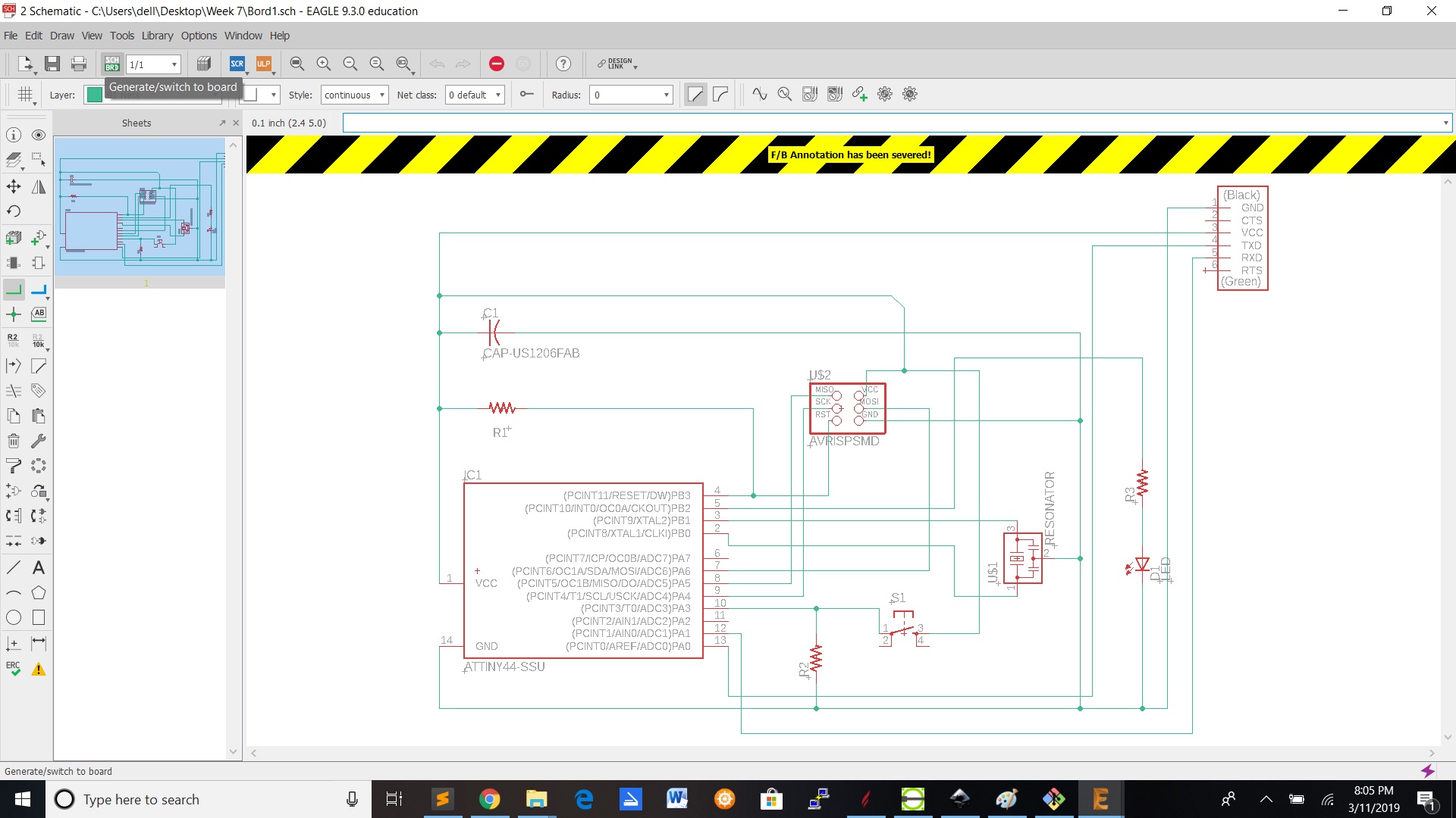
If you're done connecting the components ,you can click on the generate/switch to board on the top panel.
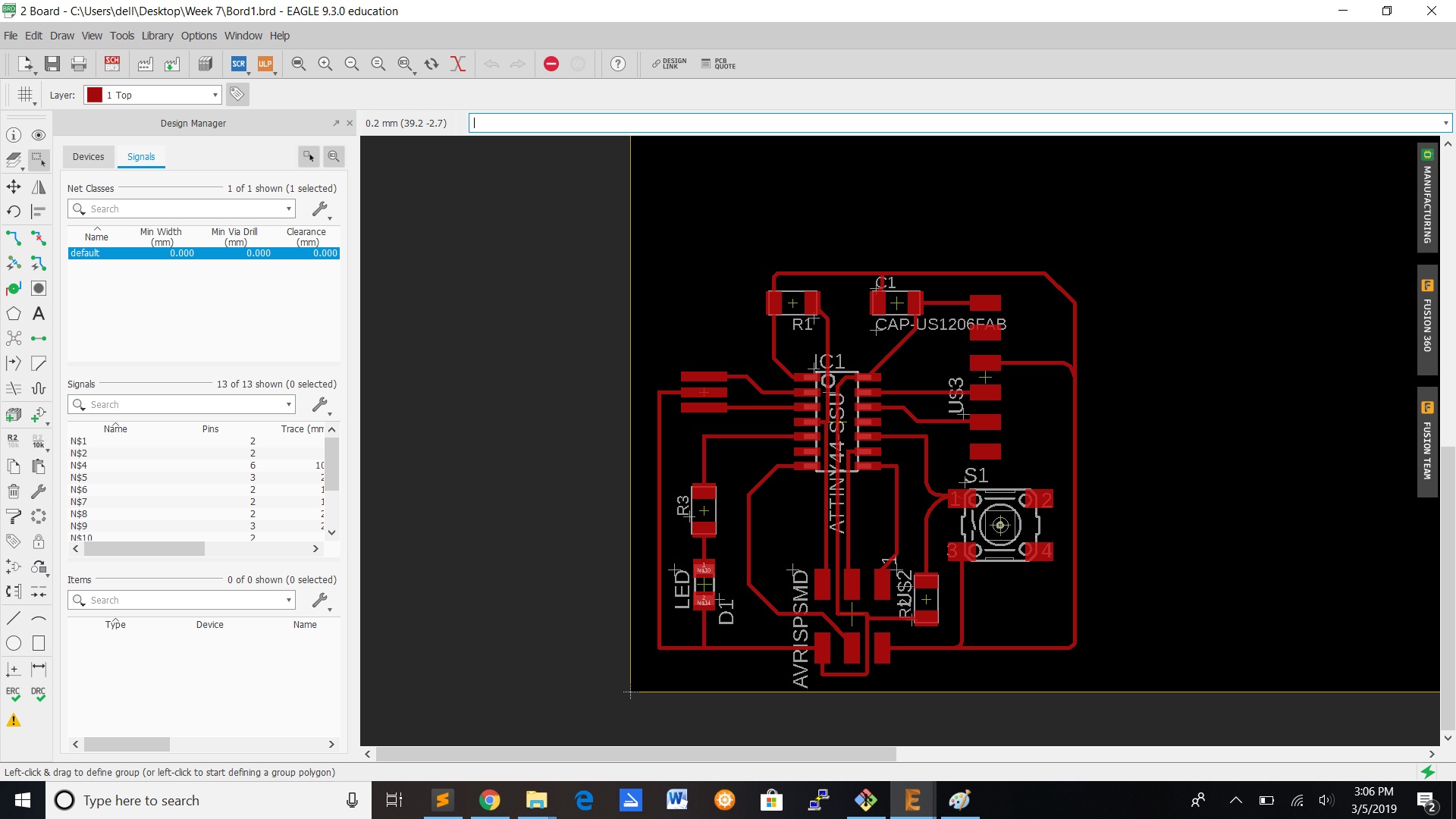
1.After you click on the generate/switch to board on the panel.You will get this window with the components not in their place.So to put them in place you have to select them and move them.
2.Click on the move button and move your component.
3.To connect your components to each other ,select the route option and then click from component to component.When you click on a component with route it also shows you where you can connect the component.Route is the traces on the board from component to component.
4.When you're done with connecting the components,you can click the cam processor in the top panel to export the file.
5.If you're done connecting the components ,you can click on the generate/switch to board on the top panel.
6.Only select the top copper and then process job and export file in .gbr format.The top copper is more to cut the traces on the board.
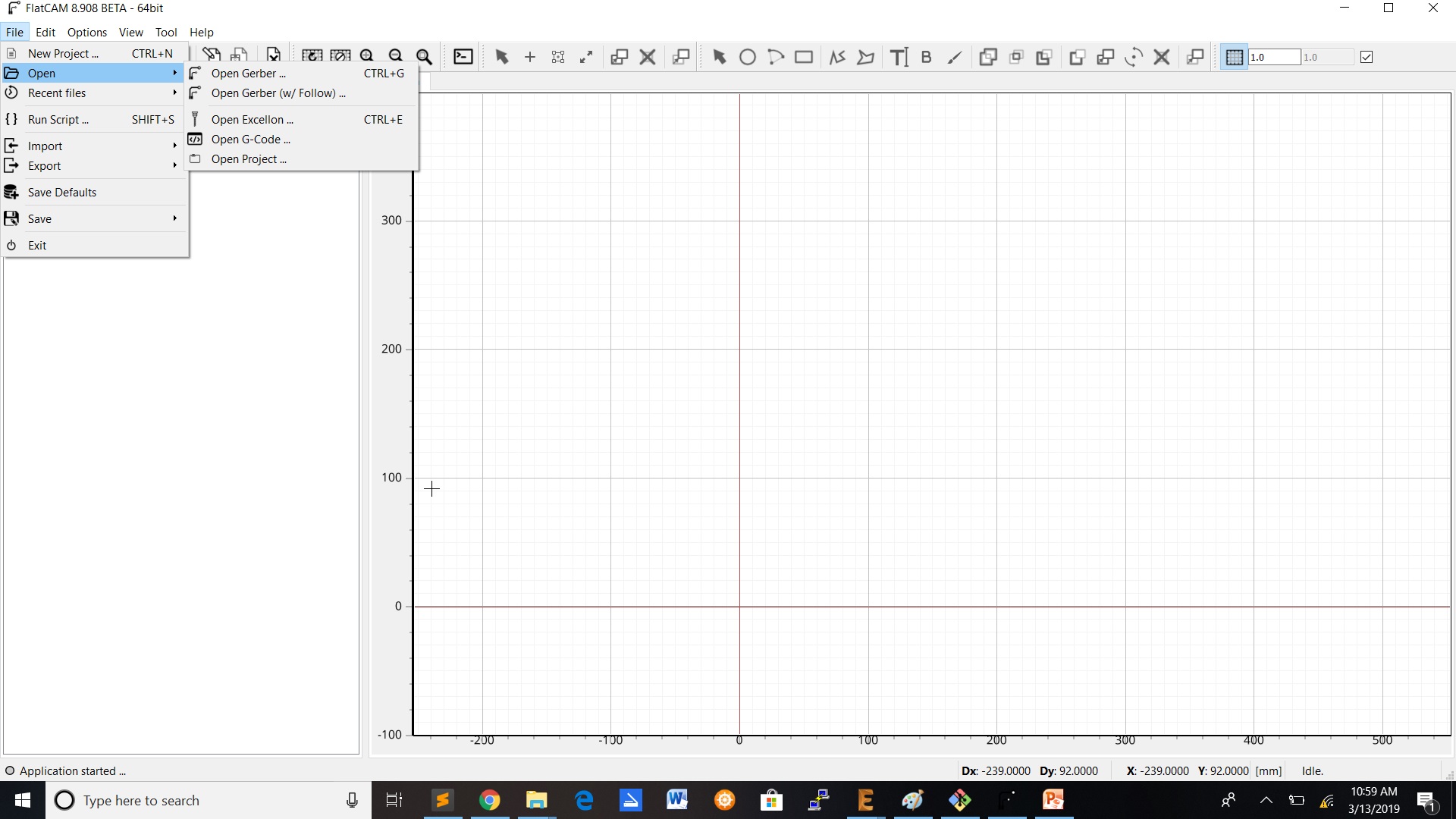
Import/open your file into flatCAM and also add the following values.
| FlatCAM | Value |
|---|---|
| Tool dia | 0.4 |
| Cut Z | -0.2 |
| Travel Z | 2 |
| End move Z | 2.0000 |
| Feed Rate(X,Y) | 0.3 |
| Feed Rate Z plunge | 0.5 |
| Spindle speed | 12000 |
| Cut out | Value |
| Tool dia | 8.3 |
| Margin | 1.5 |
After adding the values in flactcam,you have to generate the parameters to save/export your file in .NC format.(G-code)
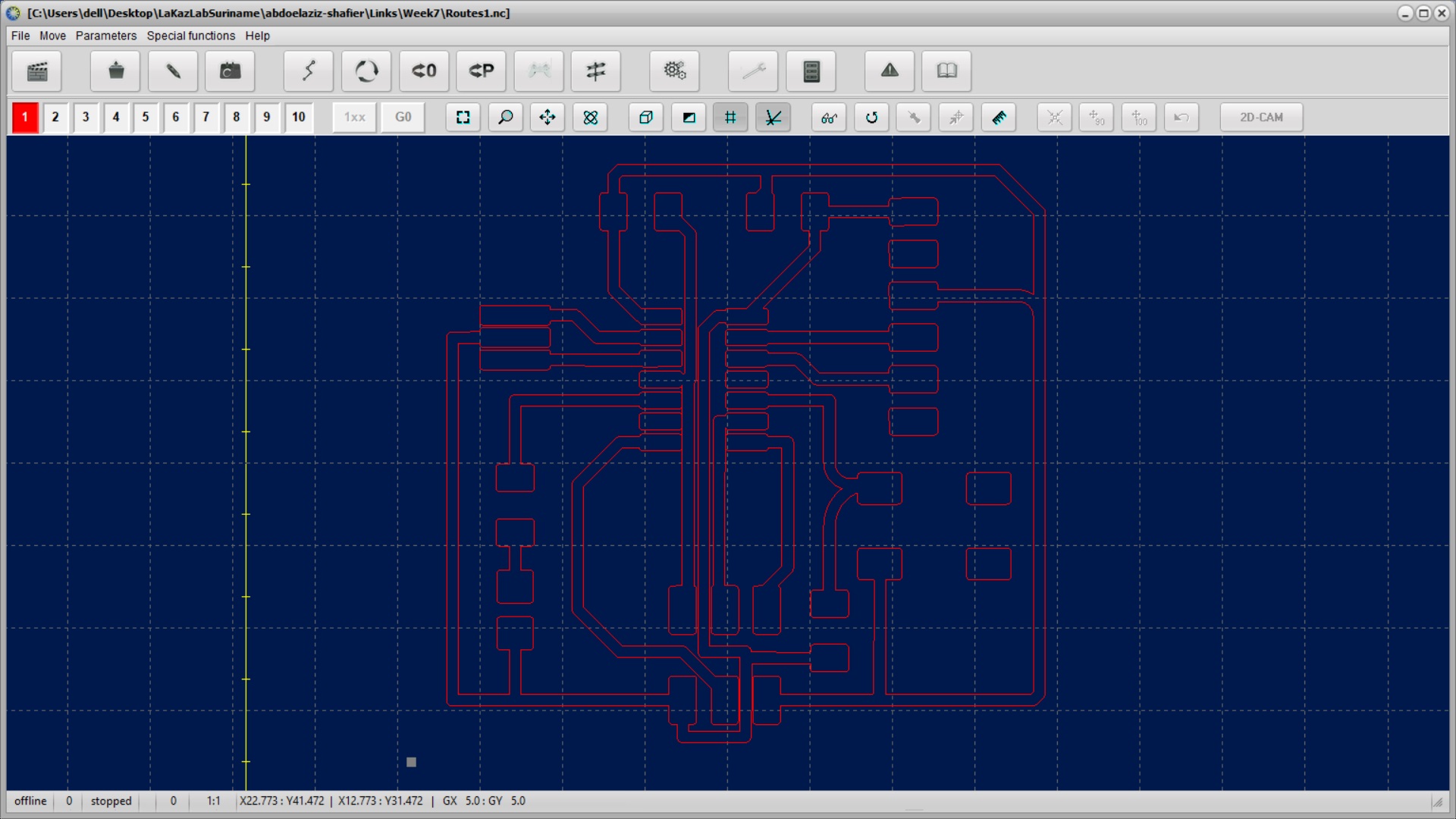
Import the file into Winpcnc and then change your parameters.Check the invert-z box in the parameters option ,the start and end position to zero point and also to go back to zero point position.
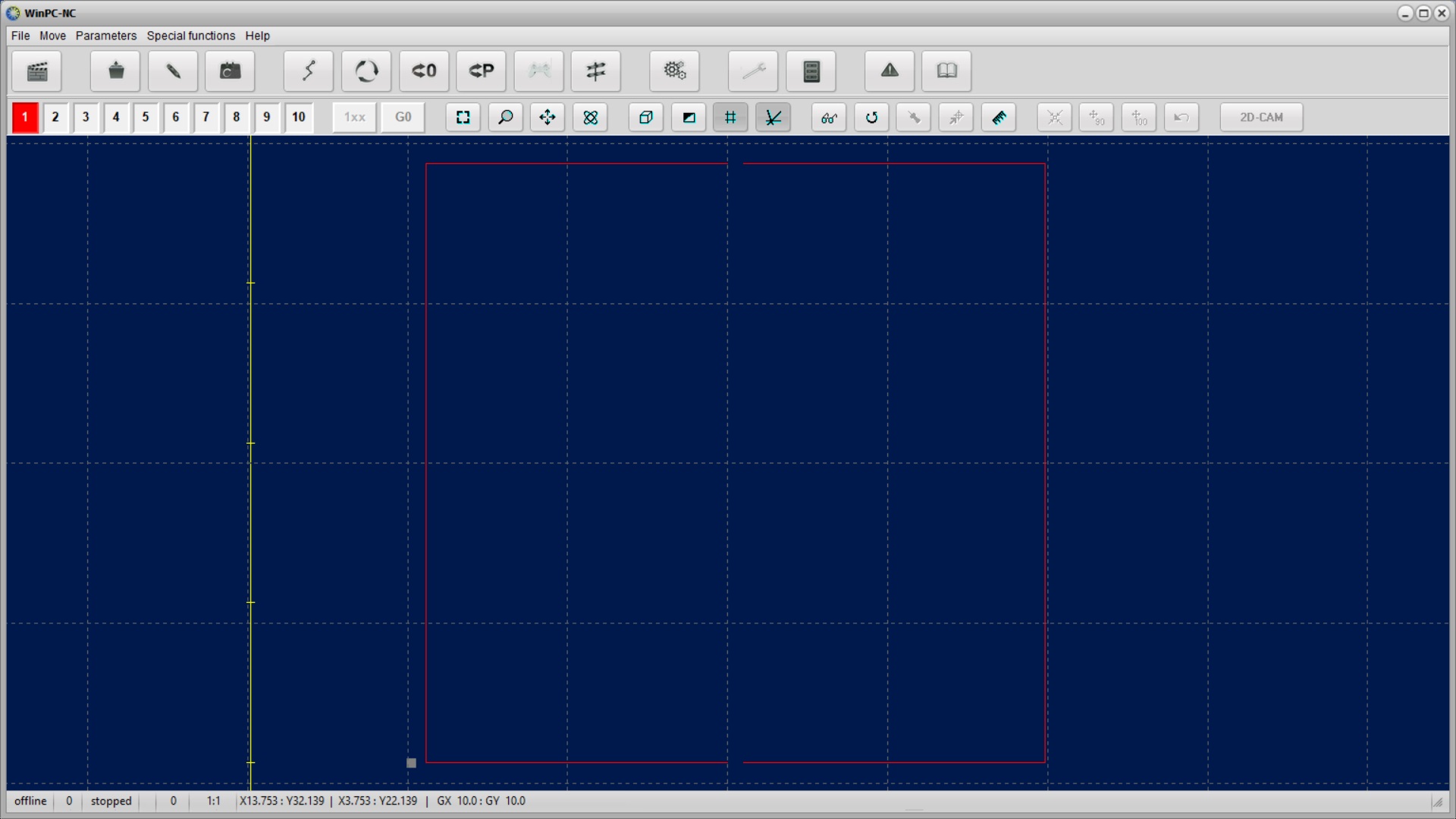
Also import the cut trace to cut you board out.The cut out trace is to cut your board out of the board and that will cut in passes.Passes are steps that are taken in how much cuts it has to make to cut a object.
*Tip = Use double sided tape on your board,so that your board doesn't slide when milling.
The components I soldered :
1)2x10K ohm Resistors
2)1x1K ohm Resistor
3)1x Microcontroller Attiny 44a
4)1x Resonator 20 MHz
5)1xAVRISP Connector
6)1x 6*1 pin Connector
7)1x 1uF capacitor
Some problem i had after soldering the component are that i'm getting shortage and i fixed it by cleaining up the traces.
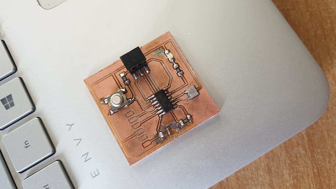
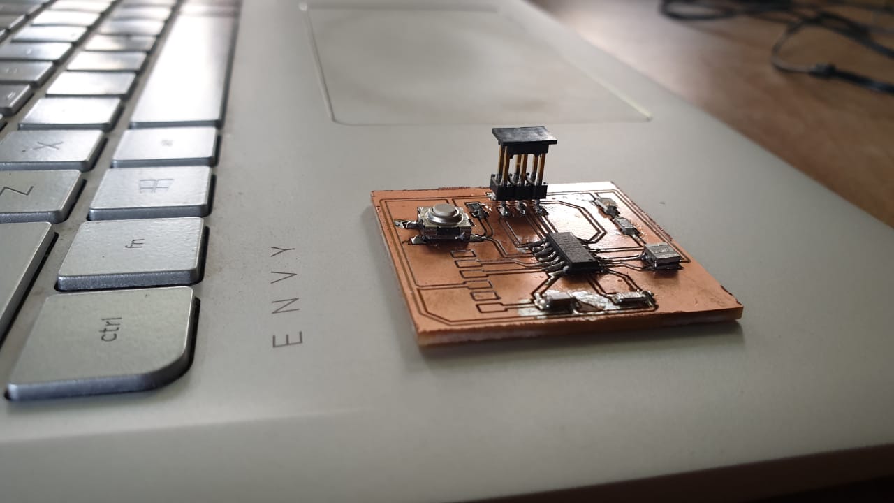
After soldering the components on the board,your board has to be like this.
Programming the Board
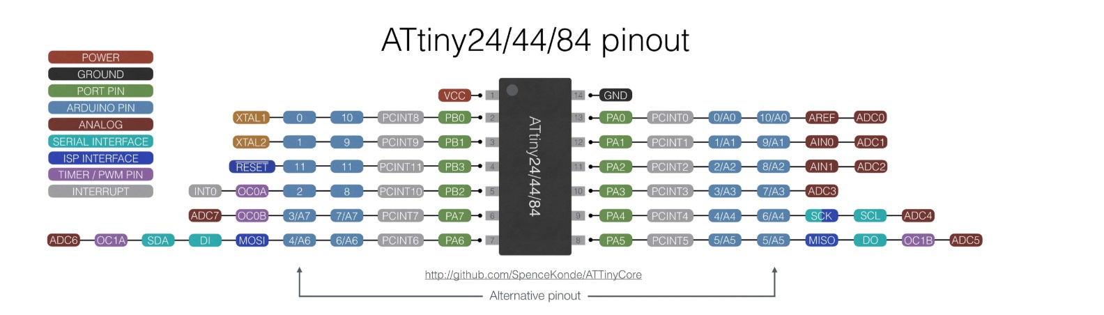
The attiny 44 pin introduction.
The Atmel® ATtiny24/44/84 is a low-power CMOS 8-bit microcontroller based on the AVR enhanced RISC architecture. By executing powerful instructions in a single clock cycle, the Atmel ATtiny24/44/84 achieves throughputs approaching 1MIPS per MHz allowing the system designer to optimize power consumption versus processing speed.
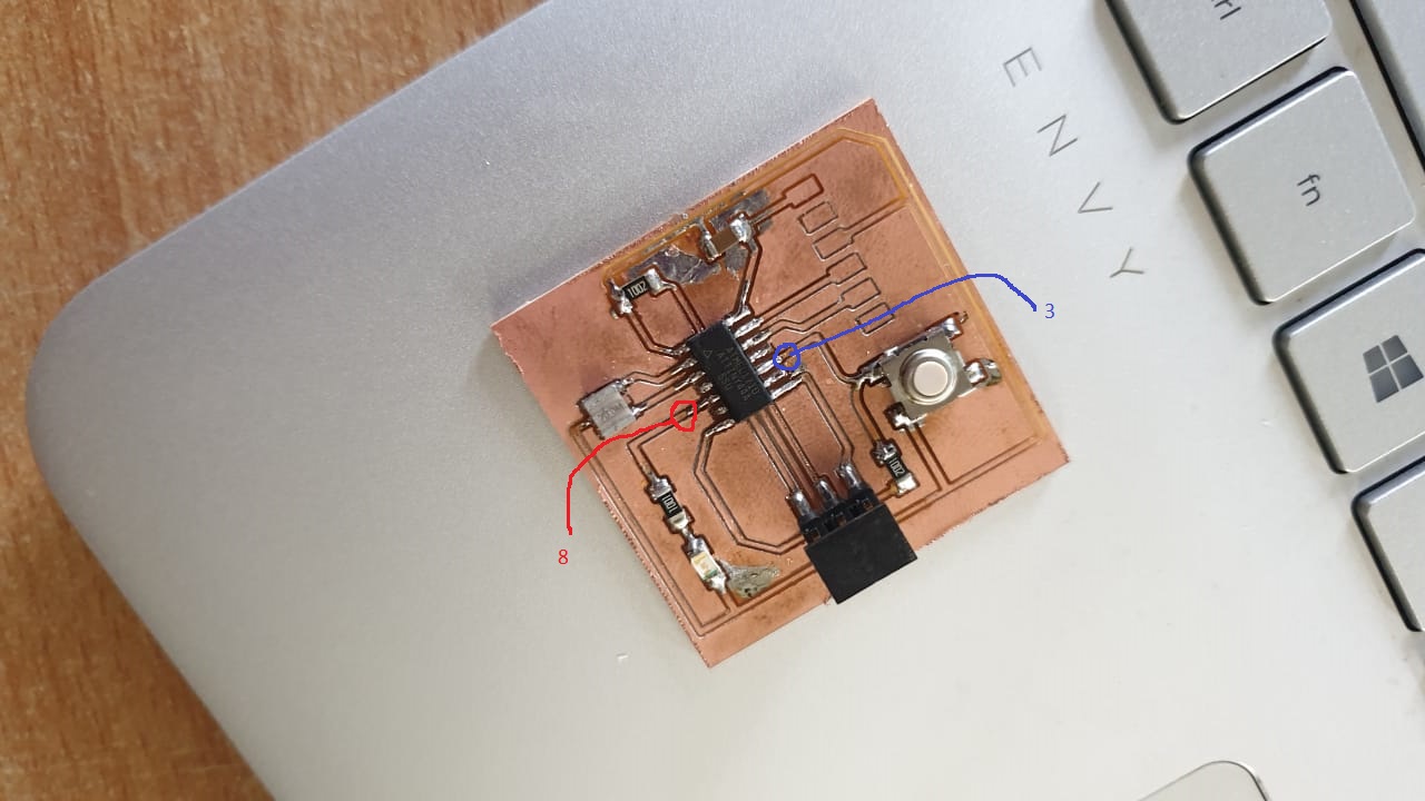
Led Pin is 8 and Switch Pin is 3.The measures i made with the volt meter is:
| Component | Value |
|---|---|
| Microcontroller | 7.9 |
| Switch(Button) | 7.7 |
| LED on | 5 |
| LED off | 0 |
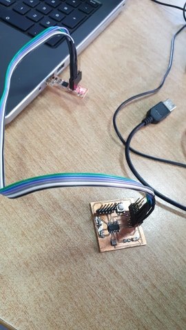
Before you connect your board you have to know where your VCC(Voltage Common Collector) and GND(Ground)is on both boards.If you know where the VCC and GND is you can connect the board with female jumper wire connectors.
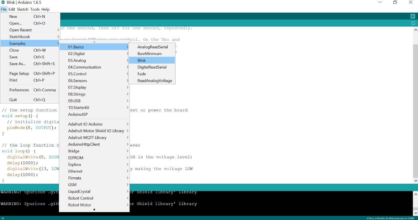
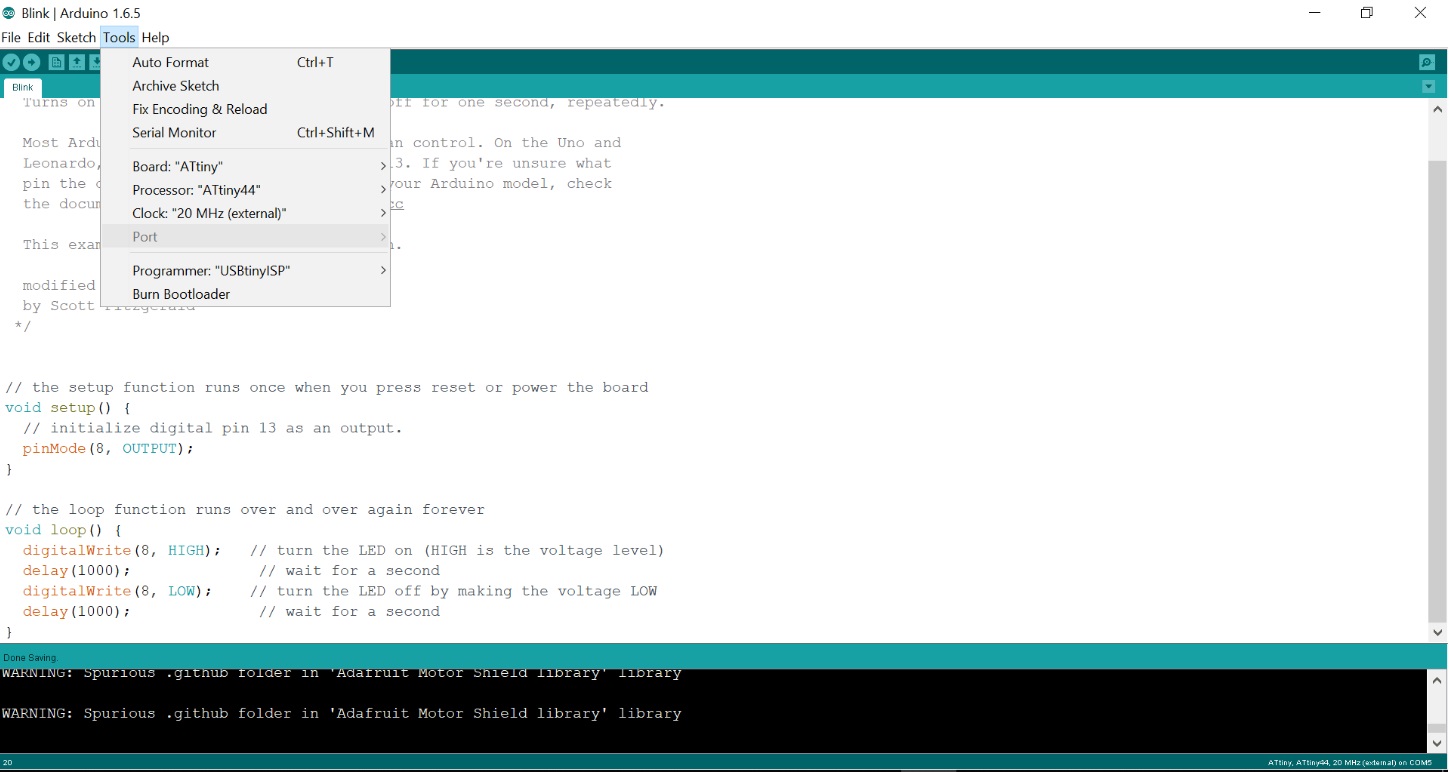
Install the arduinno ide on your computer and open it.Select file ->Examples ->Basics ->Blink and also install the library https://raw.githubusercontent.com/damellis/attiny/ide-1.6.x-boards-manager/package_damellis_attiny_index.json.After doing that you have to select your programmer in the tools option.You have to select your board,the processor,the clock and the programmer.
Power your board and run the bootloader.after running the bootloader,you can load your code.
The board is working and the Led is Blinking.
Files
Echo Hello World BoardCut out Board
Eagle Board cam
Eagle Board
Eagle Schematic
Arduino LED Blink